
01 / Elastic element
Agree alloy, heat-treatment condition and dimensional inspection for the approved design.
SERIAL-LINKED MEASUREMENT EVIDENCE
Agree the force points, reference chain and sensor–conditioner association before ordering. A useful calibration record explains what was measured, under which conditions and with what uncertainty.
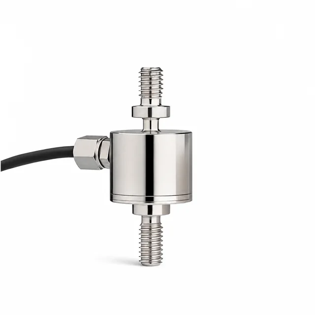
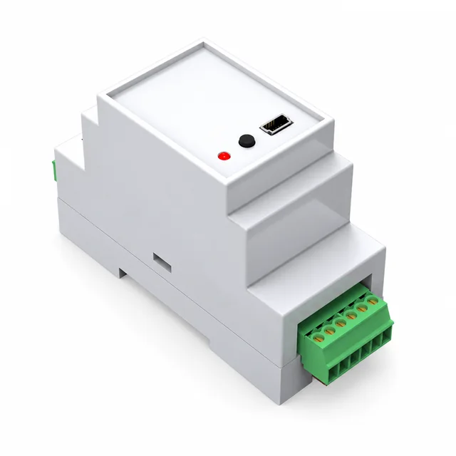
SENSOR S/N ↔ CONDITIONER S/N
Hardware constructions shown for planning. Agree serial pairing, force points and scaling in the supplied records.
Define zero and the requested 25%, 50%, 75% and 100% full-scale points for each direction. Agree loading/unloading, repetitions, preload, units and acceptance limits for the intended measurement. A single non-linearity number does not include every uncertainty contribution.
| Record field | What the engineering review should establish |
|---|---|
| Sensor identity | Serial number, part configuration, drawing revision and load direction. |
| Reference and uncertainty | Reference-force identification, calibration validity and stated measurement uncertainty. |
| Loading sequence | Zero plus agreed increasing/decreasing points for tension and compression, with repetitions and preload defined. |
| Electrical conditions | Excitation, wiring, bridge output, polarity and cable/connector arrangement. |
| Environment | Test temperature and any agreed temperature-compensation evidence or operating limits. |
| Paired system | Conditioner serial number, gain/filter settings, N or lbf scaling and output protocol. |
TRACEABILITY IS A PROPERTY OF THE RESULT
NIST describes metrological traceability through a documented chain of calibrations, each contributing uncertainty. A familiar laboratory name or certificate heading alone does not establish that the installed measurement is suitable for your application.
Request the current calibration scope and reference evidence with the quotation. Website diagrams are not issued calibration records, and no laboratory accreditation is implied.
NIST traceability policy and checklist ↗Agree the resistor value, connection method and expected response for the specific bridge and conditioner. Record excitation, gain and filter settings so a later check can be compared under the same conditions.
A resistor check does not apply a physical force. Mechanical damage, changed alignment and fixture loads still require separate investigation and, where needed, an applied-force recalibration.
Specify the paired conditioner →MANUFACTURING AND TEST HANDOFF
Use this review framework to define the records for your order. Test durations, overload limits, seal performance and compensation results belong to the approved configuration and actual test report.
Agree alloy, heat-treatment condition and dimensional inspection for the approved design.
Identify the bridge, bonding/curing process and inspection records appropriate to the selected force range.
Define thermal and mechanical conditioning, cycle counts and acceptance criteria; record the actual procedure.
Record zero balance, span and temperature-related checks under their stated conditions.
Inspect strain relief, insulation and ingress testing against the specified connector and environment.
Document reference load, loading direction, points, output and evaluated errors.
Link the sensor and conditioner S/N, scaling, configured output and agreed shunt response.
For an annual swap request, identify the installed sensor and conditioner, required calibration interval and spare quantity. Confirm the replacement acceptance check, price, old-unit return or retention and regional service terms in the quotation.
Include an annual pre-calibrated swap request ↓No. Agree the measurement result, reference calibration chain, uncertainty and test conditions. The serial-linked certificate must identify the scope actually performed.
A shunt check exercises the electrical measurement chain against an agreed resistor response. It does not apply a reference force or verify the mechanical installation, load path or overload stops.
Include the current configuration and serial number, calibration interval, conditioner and spare quantity. Availability, pricing, old-unit handling and acceptance criteria are confirmed in the quotation.
ENGINEERING RFQ / SAMPLE REQUEST
Include both thread ends, working and peak force, available space and the signal your controller expects.
Company and university email domains are preferred. Prototype and research inquiries are welcome.
inquiry@inlineloadcell.com ↗