
TECH NOTE 01 / Mechanical installation
How to mount an inline load cell on a linear actuator
Identify the two complete thread specifications before choosing an adapter or an integrated male-female interface.
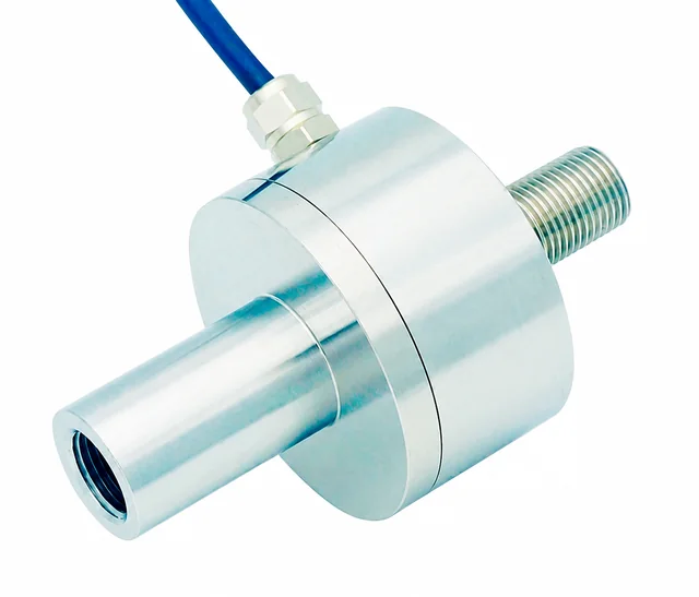
LCS Tech LCR08 manufacturer reference with both mating ends visible. Confirm the supplied threads, shoulders, alignment and installed length on the quotation drawing.
Identify the two complete thread specifications before choosing an adapter or an integrated male-female interface.
Budget the installed, engaged assembly length and cable clearance; catalogue body height alone is insufficient.
React assembly torque at the approved features and validate the axial force path in both directions.
01 / ENGINEERING DECISION
Identify both threads before choosing the sensor.
A male-to-female rod-end load cell can join an actuator rod to a fixture without a separate thread-conversion adapter, if its two interfaces are designed for that assembly. The useful decision is whether the complete stack fits and carries the intended load. A matching nominal diameter alone does not establish pitch, engagement, alignment or strength.
Read the actuator and fixture drawings first. Record male or female, major diameter, pitch or threads per inch, handedness, tolerance, usable depth and shoulder reference. A thread gauge helps identify an unknown interface; gently starting a near-matching thread is not a compatibility test.
| Callout | Nominal major diameter | Axial pitch | Assembly implication |
|---|---|---|---|
| M6 × 1 | 6 mm | 1.000 mm | Requires a mating metric pitch and appropriate tolerance. |
| 1/4-28 UNF | 6.35 mm | 25.4 / 28 = 0.9071 mm | Not an M6 × 1 mating thread. |
| M8 × 1.25 | 8 mm | 1.250 mm | Keep the pitch in the RFQ, not only “M8”. |
Supporting scope: PCB rod-end manual, 1381-01A ↗ · FUTEK LCM300 drawing FI1534 ↗
02 / ENGINEERING DECISION
Add exposed installed lengths, not overlapping thread lengths.
Draw the two shoulder planes that locate the sensor, the fixture reference and the full actuator travel. For every component, use its exposed axial contribution after the specified engagement. Adding two raw overall lengths can count the engaged thread twice; using only the sensor body can omit the adapter, locknuts and joint.
Include cable bend clearance and connector withdrawal as separate three-dimensional checks. An assembly can pass the axial sum and still collide at the cable exit or prevent a wrench reaching the locknut. Confirm these conditions at both stroke limits and through the actual joint angle.
Installed axial length = sum of exposed component projections after engagement
Supporting scope: PCB rod-end manual, 1381-01A ↗
03 / ENGINEERING DECISION
Put these interface decisions on the quotation drawing.
A complete two-end definition lets the supplier assess the request rather than infer how the actuator is mounted. The drawing should also identify which surface is allowed to carry load and which surface must remain free. Avoid using a thin cover or cable gland as a reaction feature.
| Input | Record | Why it changes the decision |
|---|---|---|
| End A and end B | Gender, full thread and handedness | Different threads may be intentional. |
| Engagement | Usable depth, free stud length and relief | A bottomed stud may load an unintended surface. |
| Locating features | Shoulder faces, locknuts and wrench flats | Controls the installed stack and torque reaction. |
| Motion envelope | Stroke endpoints, joint angle and cable exit | Finds interference outside the sensor body. |
| Load spectrum | Working, transient, reversal and fatigue duty | Capacity is not the only mechanical limit. |
Supporting scope: PCB rod-end manual, 1381-01A ↗
04 / ENGINEERING DECISION
Keep installation loads out of the sensing flexure.
Use the mounting method in the actual sensor manual. Plan how the fixture is turned and how torque is reacted before connecting the final assembly. Do not transfer a torque value from a different sensor, thread size or fastener chart. The load-cell structure and its approved reaction features govern the operation.
PCB’s rod-end manual illustrates centered axial loading and the use of alignment components. That is a useful installation principle, not evidence that a joint removes every side force. Misalignment, constrained cable motion and actuator acceleration still need evaluation in the final mechanism.
- Support the actuator and fixture so their weight does not pass through an unprotected micro-force sensor during assembly.
- Identify the approved fixed end, active end, reaction features and tightening procedure.
- Check engagement and shoulder contact without bottoming on a non-loading surface.
- Route and restrain the cable independently of the moving load path.
- After assembly, verify zero, polarity and small known forces in the intended directions before the full operating sequence.
Supporting scope: PCB rod-end manual, 1381-01A ↗
05 / ENGINEERING DECISION
Worked example: compare two installation stacks.
This is a hypothetical packaging comparison, not a dimensioned MT-ILC product. Assume an available installed length of 50 mm. Every entry below is an exposed contribution after engagement. The adapter solution exceeds that space; the integrated-interface request has only 2 mm remaining and still needs cable, tolerance and motion checks.
The 6 mm difference belongs to these assumed assemblies. It is not a universal percentage saving and does not show that a specific sensor can be manufactured or supplied at the assumed dimensions.
| Exposed contribution | Sensor plus adapter | Integrated MF request |
|---|---|---|
| Sensor | 20 | 28 |
| Locknut allowance | 8 | 6 |
| Thread adapter | 12 | 0 |
| Joint / fixture | 14 | 14 |
| Total | 54 | 48 |
| Margin within 50 mm | −4: redesign | +2: continue full envelope review |
06 / ENGINEERING DECISION
Worked example: reversal changes more than the force sign.
Assume a 500 N axial force acts 1 mm away from the intended axis. The associated bending moment is 500 × 0.001 = 0.5 N·m. This arithmetic does not establish an allowable moment; it identifies another load to compare with the proposed design’s limits.
A push-only test may not reveal motion across thread clearance, a joint seating change or cable-induced force during reversal. Log loading and unloading, observe the shoulder contacts and compare fixture position with force. An integrated MF sensor does not by itself guarantee zero axial backlash.
| Check | Observe | Acceptance evidence |
|---|---|---|
| Steady axial load | Force, fixture alignment and cable reaction | Approved force and side-load limits. |
| Push-to-pull reversal | Dead travel, reseating and zero return | Application-specific displacement/force allowance. |
| Stroke endpoints | Cable bend and joint angle | No interference through the complete motion. |
Supporting scope: HBK force glossary ↗
07 / ENGINEERING DECISION
A compact assembly still needs a load-path review.
An alignment bearing can accommodate an angle while still transmitting forces created by the surrounding mechanism. A shorter stack can improve packaging while increasing the difficulty of assembly or connector access. Evaluate both tradeoffs rather than selecting solely by length.
Thread strength, fatigue, installation torque, sealing and rated side load remain configuration-specific. For a replacement, also compare excitation, output polarity and calibration scaling; a mechanically acceptable stack may require an electrical change.
| Approach | Useful when | Verify before release |
|---|---|---|
| Existing sensor + adapter | Space and extra joints are acceptable | Adapter rating, engagement and stack tolerance. |
| Integrated MF request | Two different mating ends and limited space | Approved geometry, manufacturing limits and reaction features. |
| Alignment joint | The mechanism requires angular accommodation | Joint travel, off-axis loading and local clearance. |
Supporting scope: PCB rod-end manual, 1381-01A ↗
08 / ENGINEERING DECISION
Send a two-end drawing and one complete load case.
For an actuator inline force sensor RFQ, attach the actuator rod and fixture details, maximum available envelope and stroke sketch. Include working and peak force, reversal frequency, temperature and the controller input. Request confirmation of both interfaces, applicable limits and the serial-linked calibration scope.
The MT-ILC-MF configurator records the two threads and output in one engineering reference. Use it to organize the request; the accepted drawing establishes supplied geometry and performance.
Resolve the fit, signal and calibration questions.
Can I screw M6 × 1 into 1/4-28 if it starts by hand?
No. Their nominal diameters and pitches differ. Identify the complete mating callouts and use a designed interface rather than testing compatibility by force.
Is an adapter always worse than an integrated MF design?
No. A correctly rated adapter can be a practical choice when space and additional joints are acceptable. Compare the complete installed assembly, stiffness, access and cost.
What tightening torque should I use?
Use the approved procedure for the exact sensor, mating thread and joint. A general fastener torque chart does not establish a safe torque through a sensing flexure.
Does a rod-end bearing eliminate side load?
It allows specified angular motion. The surrounding constraints can still produce lateral forces and bending, so evaluate the actual mechanism.
Does a male-female interface guarantee zero backlash?
No. Thread fit, locknuts, joint clearance and preload determine reversal behavior. Verify the assembled load path under the intended force cycle.
Can the cable be used to hold the sensor during assembly?
Use the approved mechanical holding features. Cable tension or torsion can damage the connection or create parasitic force, particularly at small capacities.
ENGINEERING RFQ / SAMPLE REQUEST
Send the load case.
Define the interfaces.
Include both thread ends, working and peak force, available space and the signal your controller expects.
Company and university email domains are preferred. Prototype and research inquiries are welcome.
inquiry@inlineloadcell.com ↗